The new product of the Turris router series is called MOX and it is conceived as a modular system. A number of additional modules can be connected to the basic CPU of the MOX A module, allowing the users to use only the features they need, without the peripherals they have no use for yet. And, of course, they will be able to extend the entire router in the future as necessary. Modules marked with letters A through E are now in the prototype stage, i.e. launching, testing of individual functions, but also fine-tuning the production process and preparation for serial production of thousands of devices. In this article, you will find out what prototype production looks like.
Just like the second Turris Omnia router series, Turris MOX will be produced in Lanškroun, at Morelli Electronics, s. r. o. The electrical engineering industry has a long tradition in the Lanškroun region, as it was there where Tesla Lanškroun was located, and it is now home to several of its successors. We were able to take a look at the production when the prototypes of the MOX C module with four RJ45 metallic gigabit connectors and Marvell Topaz gigabit switch were line-produced. Before the production itself, it is necessary, on the basis of data from hardware developers, to make PCBs – Printed Circuit Boards, and buy components to be installed onto them. We have these boards manufactured in China, mainly due to speed and price. Production and delivery to the Czech Republic takes about two to three weeks.
Components and all parts for prototypes are purchased at one of selected online stores where they are in stock and instantly available. If everything goes smoothly and the shipment is not intercepted by customs, we have the components available within three days of ordering.
Serial production, however, is something else entirely. There is a difference when you need hundreds of capacitors or two million of them. Prices and especially delivery times are significantly different and unfortunately rather unpredictable nowadays. The full description of component purchase would be enough to make another article, which we may publish some other time.
So we have everything we need to produce our prototypes, our prototypes are included in the production plan and we can launch the production. We start by placing SMT components, i.e. surface-mount components. Simply put, these are the small parts without visible outlets. That means almost everything on MOX C except Ethernet connectors.
The first step is to apply the solder paste to the board. The boards are not supplied separately, but in the so-called panels, from which they are removed only after the placing. Thanks to the panels, PCBs can be placed on conveyors of individual machines, so each step is implemented on a larger number of boards at the same time. In our case, there are four MOX C boards in one panel. The application of the solder paste is done by screen printing. In addition, the screen printing machine has its own inspection, which checks the thickness, uniformity, quantity and shape of the paste application at each point on the board.
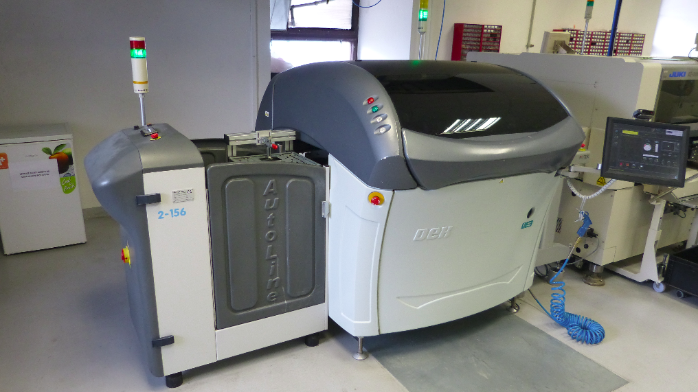
Screen printing with attached input feeder

The inside of the screen printing machine
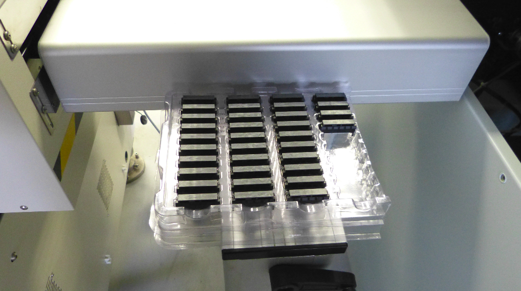
Boards placed in the input feeder
After coming out of the screen printing machine, lead-free gray solder paste is applied on all SMT parts.
Conveyer at the screen printing output
The next step is placing the components in the applied solder paste. This step is carried out in the pick-and-place machine. The components are supplied in several types of packaging, but mostly in so-called reels.
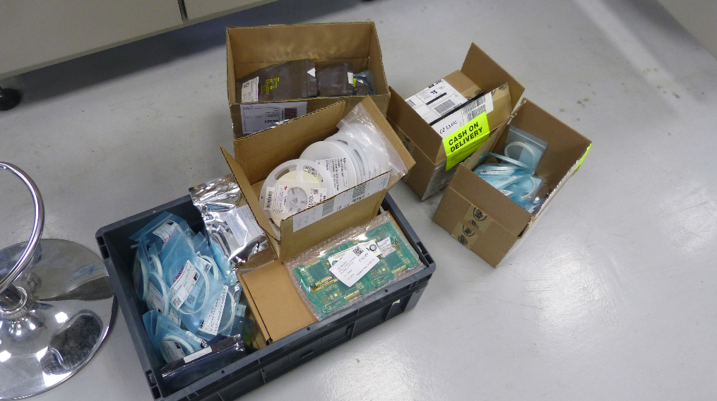
Components to be mounted on the MOX C prototype
These reels are placed in a feeder that is snapped into the pick-and-place machine. This machine then places the individual components in the right place based on the program. This program is created based on input provided by our hardware developers.
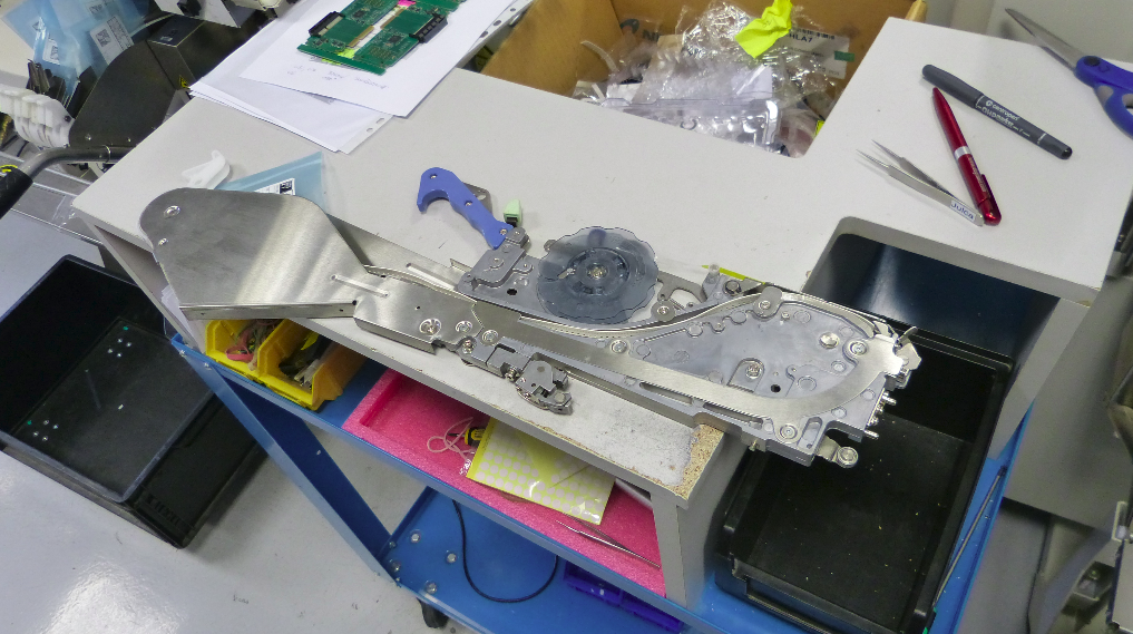
Feeder with a wound capacitor reel
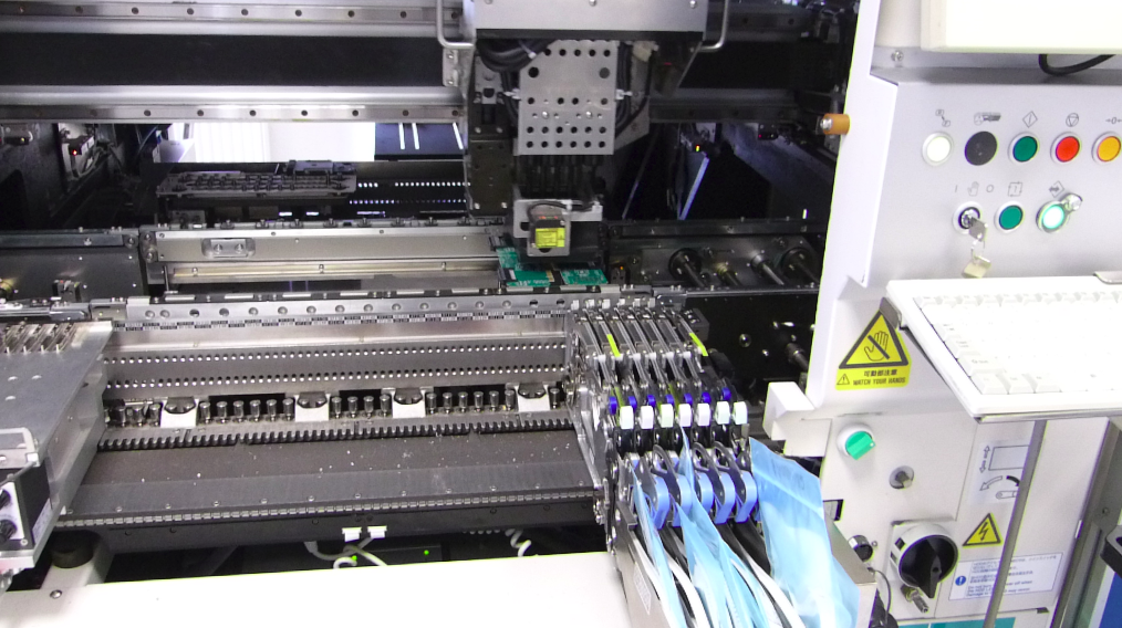
The inside of the pick-and-place machine with a couple of feeders in the bottom right corner
The pick-and-place machine has also the ability to check individual components for suitability – it calculates the number of outputs per component and compares it to the stored pattern in the program. This may reveal a possible error in the feeder’s charge or component error.
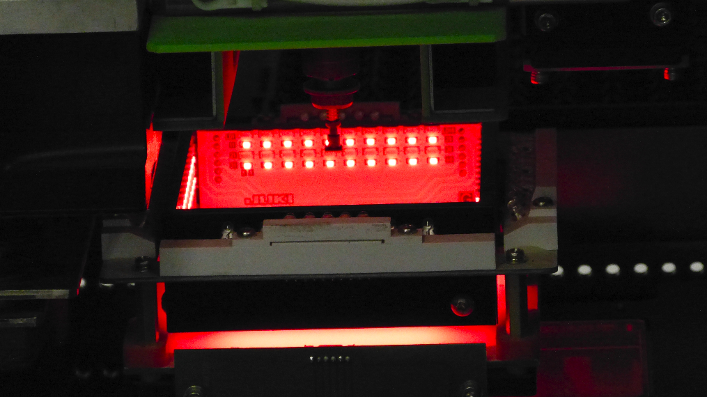
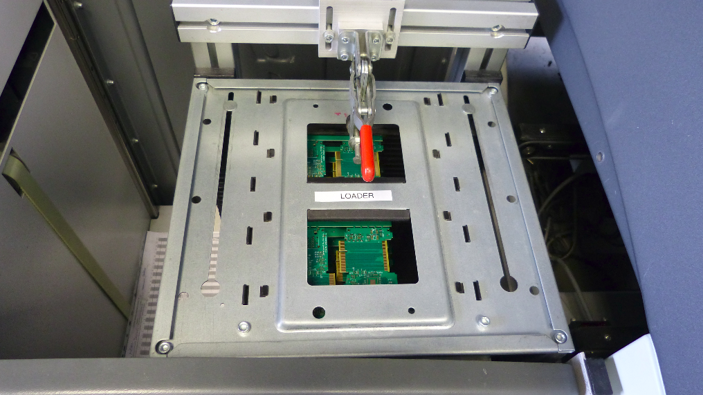
Component check – cameras are on
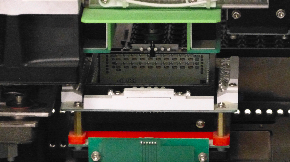
Component check – cameras are off, it is possible to see the pipette for component gripping
The operation of the pick-and-place machine is not easy. It takes about two months for the operator to learn the basic operation and a whole year to handle all procedures and machine programming. And they will continue to learn for all their life. The price for the modularity of MOX is the use of Straddle mount connectors for connecting the individual modules. Their mounting and soldering is not a simple matter and cannot be automated in our conditions. In our case, they are hand-placed using a special tool made by Morelli.
A package of straddle mount connector
In the production where MOX C prototypes were fitted with components there are two place-and-pick machines placed one behind the other. In the first, a part of components is mounted while the second machine takes care of the rest of them. Thanks two this, two panels can be fitted at once instead of just one.
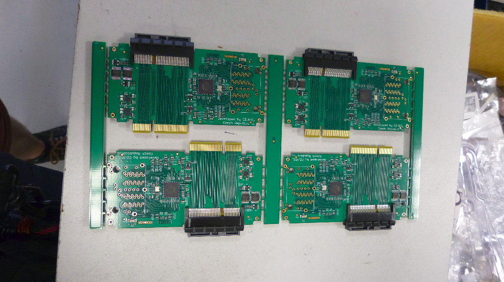
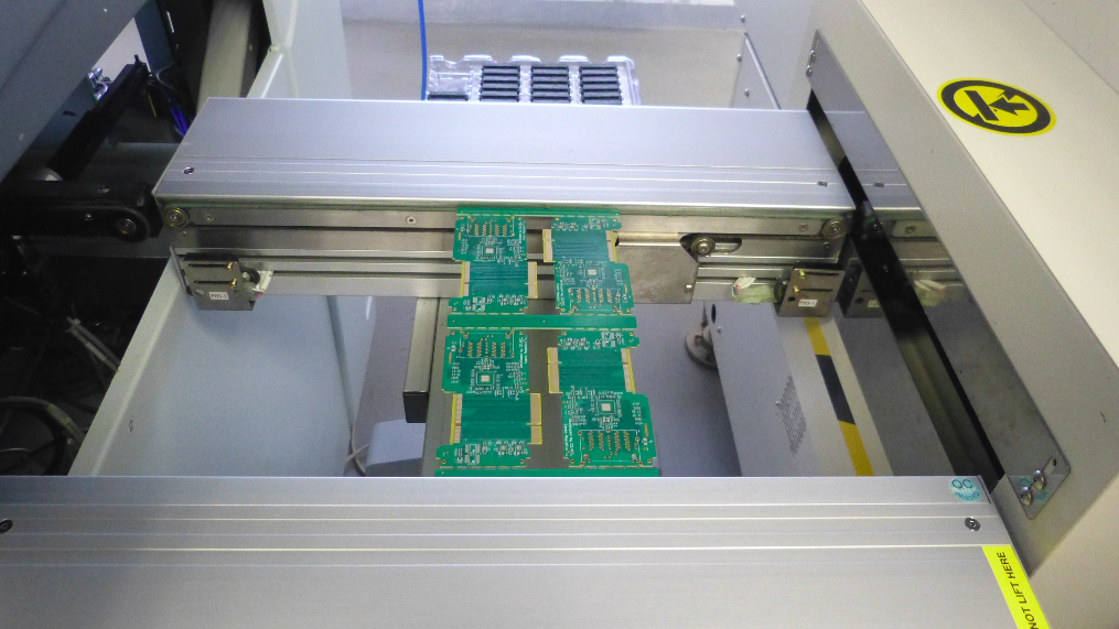
Fitted board after coming out of the first pick-and-place machine

Board completely fitted with SMD components

The assembly line; from the left, there is a screen printing machine and two pick-and-place machines
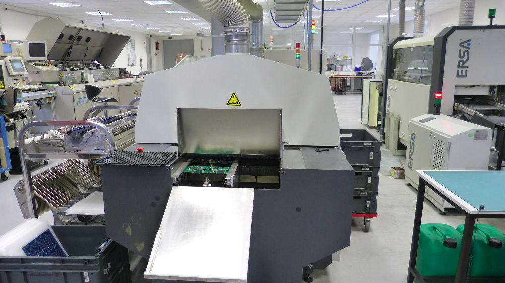
The fitted boards are then sent into the reflow oven, where the solder paste is melted and individual components are conductively connected to the board. There are two reflow ovens in Morelli, but unfortunately, the larger one, belonging to the line we use, was out of service at the time of our visit. We could at least take pictures of its insides. This larger oven has starting power of 45 kW, and it takes 20 minutes to heat it up.
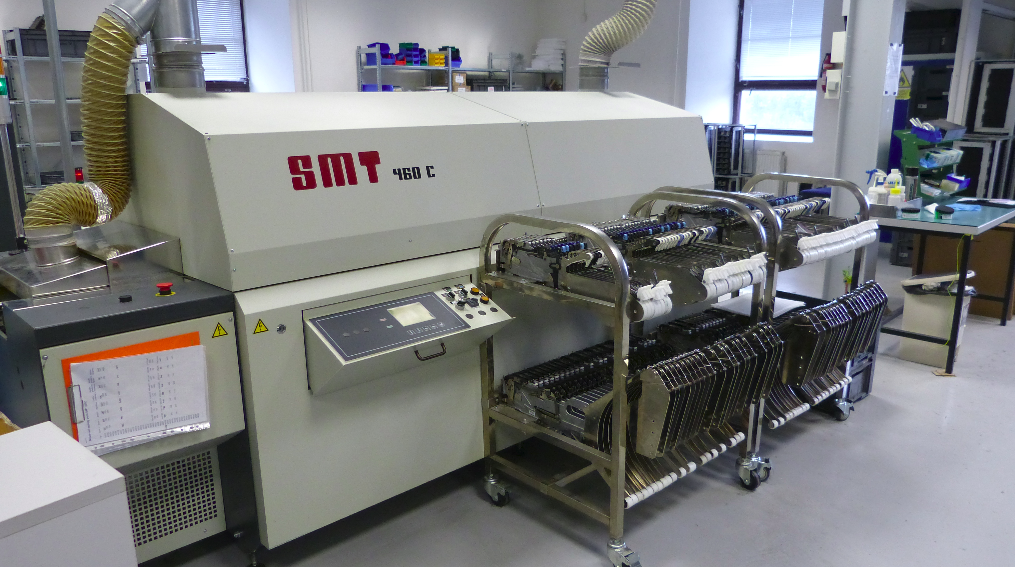
A reflow oven used to produce the MOX C prototypes, with a cart for pick-and-place machine feeders in the front
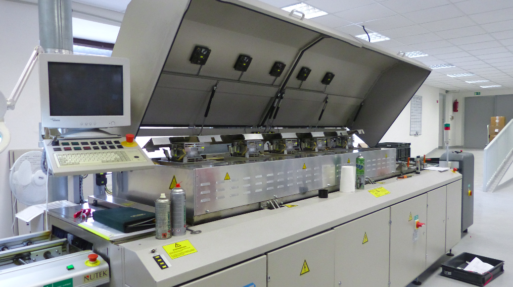
An open reflow oven, in which Turris MOX will be produced
Boards coming out of the reflow oven
After placing and soldering all components on SMT lines comes AOI – Automated Optic Inspection. Here, all components are tested for correct soldering and positioning. You can check out AOI in action in the following video.
The last step for our prototypes is the installation of an Ethernet connector. In series production, so-called wave soldering will be used, but for a small number of prototypes it is cheaper to install and solder the connectors manually.
Assembled modules are packaged into anti-static bubble wrap and sent to CZ.NIC into the hands of our developers, who bring them to life and begin testing their functionality. But this is a story for another time.
fascinating stuff guys and thank you for the walk through
Thanks for sharing! Interesting manufacturing site. How big are their production capacities?